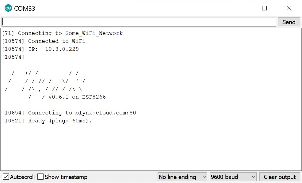
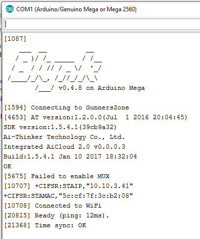
Define Blynk_print Serial
Enter the following WiFi credential and Authentication token in the code. Every WiFi BluetoothBLE Ethernet and Serial device is able to conn.
Blynk Board Arduino Development Guide Learn Sparkfun Com
In this IoT Project we are interfacing 40Kg load cell to the NodeMCU ESP8266 using the HX711 Load cell amplifier moduleHX711 is a precision 24-bit analog to digital converter ADC designed for weighing scales and industrial control applications to interface directly with a bridge sensor.
. WiFi Name at WiFi Name. The Variable Resistor and LDR values will be displayed on the Gauges using the Blynk. GPIO-2 ----- Not connected open.
An ultimate tutorial for beginners on how to connect and use an ESP8266 via Arduino and program it to blink an LED using the Blynk app. WiFi Password at WiFi Password. Well IoT is trending everywhere and is one of the greatest things that can be used to make life easier.
You can create your own interfaces using the free Blynk App. There are many IoT based home automation projects available on the internet but none of them provides you an option to control the speed of fan over the internet. We are using GPIO25 in.
Define BLYNK_PRINT Serial. I am also getting the same. Define Template ID and Device Name on top of your firmware before any includes.
This is the complete circuit diagram for this home automation project. Provision your board via Dynamic Provisioning flow and add it to your account using Blynk app. And the GPIO pins SD3 D3 D7 RX connected with switch or push buttons to control the 4 relays manually.
Nodemcu with Arduino In this tutorial you will learn how to do Serial communication between Arduino and Nodemcu esp8266 wifi moduleFor the demonstration purpose in this project LDR and variable resistor will be monitored using the Blynk Application. The circuit is very simple I have used the GPIO pins D1 D2 D5 D6 to control the 4 relays. After programming remove the serial Arduino cable and plug it again and take out GPIO-0 from GND and just interchange the connection of RX and TX that is RX connect to TX and TX connect to RX.
In this project we will learn how to make our own IoT Based Electricity Energy Meter using ESP32 monitor data on the Blynk ApplicationWith the current technology you need to go to the meter reading room and take down readings. Upload this sketch into your test board. Then click on the upload button to program the NodeMCU board.
To automate this we can use. Define BLYNK_PRINT Serial include include include Output Variable. The HX711 load cell amplifier is used to get measurable data out.
Blynk is an Internet of Things platform which makes controlling hardware remotely and visualizing its data very easy. Then we will define the variable of data type int called led_gpio. Using the Sofware serial library we can define multiple serial ports without any problem.
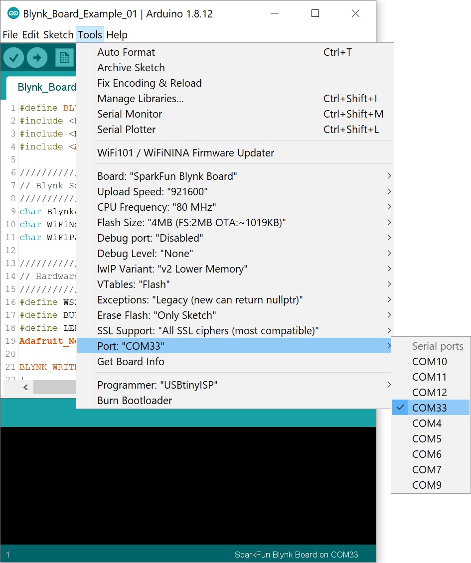
It will save the GPIO pin through which we will connect our LED. Auth Token sent by Blynk at AUTH TOKEN Then Goto Tools and select the board as NodeMCU 10 ESP-12E and the proper PORT in Arduino IDE. So here in this project well be making an IoT fan speed control circuit to control the speed of a regular.
I have used the INPUT_PULLUP function in. Thus monitoring and keeping track records of your electricity consumption is a tedious task. Define your physical button and LED if needed.
I have explained the circuit in the tutorial video. Do 1 thingy Define server address blynkcloud. So in this project the Arduinos default serial port will be used for sending the information to the computer serial terminal while the with the other serial port Nodemcu esp8266 wifi module will be connected.

Blynk Control Rgb Led Colors Rgb Led Led Color Led
Blynk Print Serial Where Does This Magic Happen Projects Made With Blynk Blynk Community
Blynk Print Serial Solved Blynk Community
Blynk Board Arduino Development Guide Learn Sparkfun Com
No comments for "Define Blynk_print Serial"
Post a Comment